
Introduction
The first four worksheets implement exactly the same analytical solutions as the view factor charts normally printed in heat transfer textbooks (1, 2). Unfortunately, those charts rarely provide better than two-digit accuracy. Moreover they provide no visual feedback either. View factor algebra, which is commonly used in radiative heat transfer analysis, often involves finding the difference of two very imprecise numbers. These functions implemented here return values having an accuracy of four or five digits. In addition, these four worksheets automatically draw a scaled schematic of the configuration to facilitate checking of the input. Values found using the applications described here may be used in black body or diffuse-gray body radiative transfer calculations using radiosity methodology.
The fifth sheet implements calculations for rectanges in parallel planes and for rectangles in perpendicular planes. The sixth implements the Nusselt Unit Sphere method for arbitrarily-oriented rectangles. The seventh worksheet implements analytical solutions for several 2D geometries.
Radiation View Factors – Perpendicular Plates
The first worksheet computes the view factor for perpendicular plates with a common edge from the well-known analytical solution. A second VBA function draws an isometric view of the geometry on the screen. To use this workbook, the user simply inputs the length of the common edge as well as the second dimension of each of the two plates.
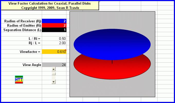
Radiation View Factors – Coaxial Disks
A VBA function finds the view factor for coaxial, parallel disks from the analytical solution. The user inputs the radii of the two disks (emitter and receiver) and the separation distance. A second function draws the disks to scale on the screen.
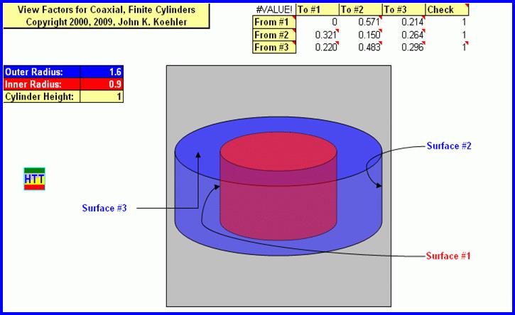
Radiation View Factors – Coaxial Cylinders
View factors for finite-length, coaxial cylinders are computed using a combination of analytical solutions and view factor algebra. The user inputs the radii of the two cylinders and their length. The coding returns all nine relevant view factors and a scale drawing.
Radiation View Factors – Parallel Rectangles
In the fourth worksheet a VBA function computes the view factor for parallel, aligned plates from the analytical solution. The user inputs the length and width of the two rectangles and their separation distance. Another VBA function makes a scale drawing of the geometry.
Radiation View Factors – Nusselt Unit Sphere Method for Arbitrarily-Oriented Rectangles
Wilhelm Nusselt developed the Nusselt Unit Sphere method as an experimental method. You can think of the hemisphere seen in this figure as a glass bowl. A NASA contractor converted his technique to a computational algorithm.

Our implementation limits the allowable geometry to two arbitrarily oriented rectangles. With some effort a competent developer could extend it to other configurations. The user enters coordinates defining the parallelograms and the algorithm returns the view factor. A plot of the input geometry allows the user to check their inputs.
Other Arrangements of Rectangles
A separate worksheet handles rectangles in parallel planes and rectangles in perpendicular planes:

VBA functions evaluate the analytical solutions for these two geometries. The figure below shows typical input and output:

The Nusselt Unit Sphere algorithm will handle these two geometries as well.
References:
Howell, J.R., A Catalog of Radiation Heat Transfer Configuration Factors
Modest, M.F., Radiative Heat Transfer, 2nd Ed., McGraw-Hill, 2003.