The usual treatment of heat exchanger thermal design and analysis is based on two analysis-based solution methods applied to the governing, coupled heat balance equations. For all but the simplest configurations, the solution of these differential equations by analytical means is challenging . For this reason, the analytical results have been graphed in non-dimensional form. Engineers have used the resulting charts routinely for the past three quarters of a century. The LMTD method is commonly used for heat exchanger design, that is, determining the required thermal size. Similarly, the Effectiveness – NTU method is used for performance calculations.
Unfortunately, the charts and equations associated with these two methods do not give a complete picture of what is happening inside the exchanger, only a single overall measure. In this two-part module, our algorithm solves the same governing heat balance equations in real time in discretized form using modern numerical techniques. The result is the same “bottom line” results as the traditional methods, but also a complete picture of what is happening within the device. In addition, not having to look up a “correction factor” manually means the user can test parameters at will until an improved design is found.
Module Description
Introduction
Our software for heat-exchanger education consists of a single module that covers both “1-D” and “2-D” exchangers:
- Use the first tab (algorithm) for double-pipe (parallel or counterflow), shell-and-tube (with multiple shell passes) and 2-pass, 2-pass plate heat exchangers. We approximate these configurations as “one-dimensional”.
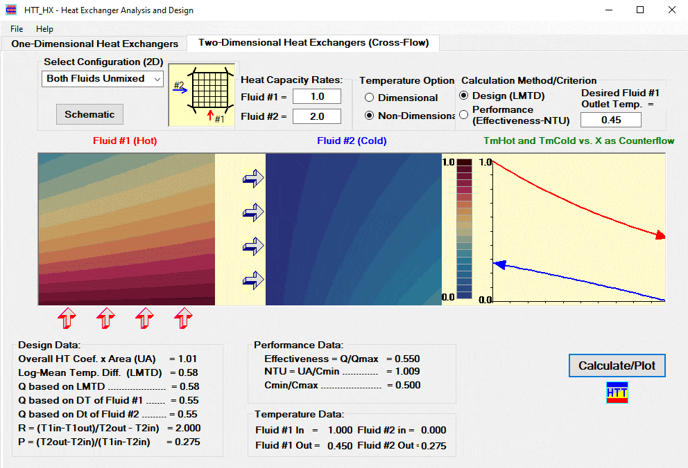
- Use the second tab (algorithm) for single-pass, crossflow heat-exchangers with the two fluids mixed or unmixed.
Both algorithms solve discretized, coupled heat-balance equations along the paths of the two fluids as they each traverse the heat exchanger. Separate algorithms (on the two tabs) are included because in one case, a coupled set of ordinary differential equations apply. In the other, a coupled set of partial differential equations governs. The results in both tabs include the detailed temperature distribution. The interface reports performance and design measures associated with the conventional (LMTD and effectiveness-NTU) methods in both cases for comparison. Samples of the main user-interface for both algorithms are shown below.
Comparison of LMTD and Effectiveness-NTU Methods
While not generally explained clearly in heat transfer texts, the two conventional methods represent two ways of solving the same basic problem.
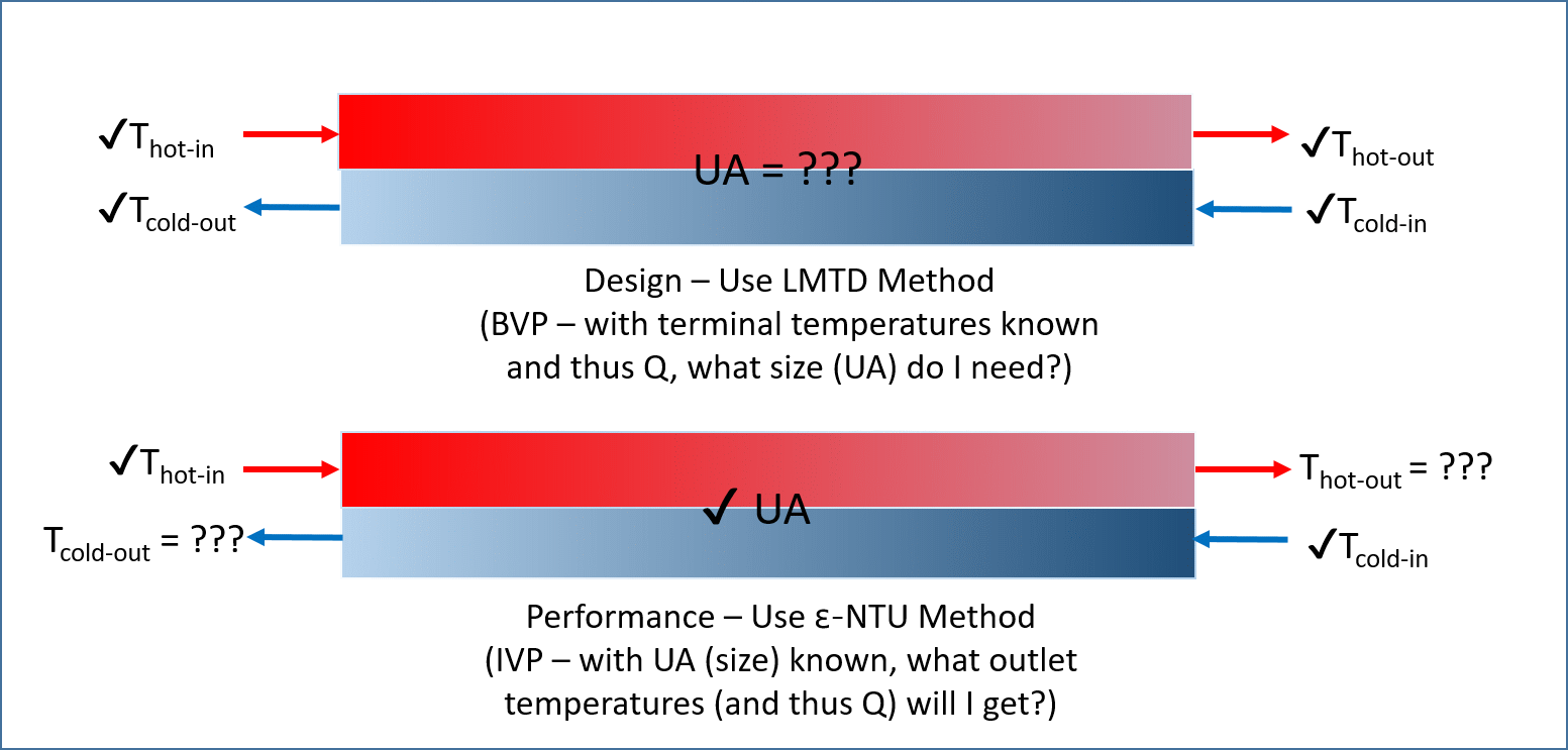
The LMTD method corresponds to the case where we need a design (thermal size UA) that transports a certain amount of heat. That quantity of heat can be determined from the difference in the terminal temperatures of either the hot or the cold fluid and the (known) heat capacity rate of that fluid. In contrast, the effectiveness-NTU method is used when the thermal size (UA) is given and the heat transferred is not, i.e., the outlet temperatures are to be found. In a numerical solution as implemented here, the difference between these approaches reduces to an extra half dozen lines of code needed to determine the UA (by iteration) in the upper case in this figure. With the conventional textbook approaches each of the two methods with associated charts and equations takes up 5-10 pages.
Geometries
Both algorithms allow for several geometric options. The single pass, crossflow heat exchanger module allows the four generic textbook options: neither fluid mixed, both fluids mixed and either one or the other, but not both mixed. A fifth selection, a two-pass geometry related to an experiment we have done in our undergraduate lab, is also included. The user selects this option in the top left corner and a small schematic of the selected geometry appears.
The 1-D option (tab seen below) allows for several generic geometries, including double pipe designs (parallel and counterflow), shell-and-tube designs and 2-pass, 2-pass plate configurations. After selection of the “Configuration” option, the user specifies a few other inputs relevant to that particular case. In the case of a shell-and-tube configuration, the thermal model uses the baffle arrangement as a convenient means of discretizing the shell for the numerical solution.

Inputs
After selecting the geometry, the user specifies the heat-capacity rates for both fluids and indicates which of the two calculation methods to use. For the “Design” option, the user specifies the desired outlet temperature of the hot fluid. For the Performance option the user inputs the product of the overall heat transfer coefficient and area (UA product). (The white background indicates input boxes on all user interfaces, while the boxes with gray background are program outputs.)
Outputs/Display
Based on this user input, the program computes and displays the temperature distributions in both fluids in a fraction of a second. For the crossflow module the interface shows the temperature distribution in both fluids in the form of color contour plots as seen above. The plot shows hot fluid flowing vertically in the leftmost plot. The cold fluid flows from left to right and appears in the center. The right-most plot shows local mean temperature difference of the two fluids, which can be helpful in assessing the quality of a design.
For one-dimensional geometries HTT_HX returns a plot of the temperatures of both fluids as a function of position. In fact, three curves appear. In the interface seen above, the light blue curve shows the temperature of the shell fluid. That of the tube fluid is plotted twice; the yellow line shows the tube fluid temperature plotted in the conventional way, i.e., as counterflow.
The third (green line) shows the tube temperature as “seen” by the shell fluid as it passes through the exchanger. So, for instance, shell fluid entering the top of the three shells used in this example first encounters fluid that is exiting the shell. Then it encounters fluid that has just entered that shell, then fluid that is nearly ready to exit, etc. This explains the “ringing” behavior in the curves. (The analytical solutions (LMTD and Effectiveness-NTU charts) are based on the exchange of heat between the shell fluid and the mean of the two local pipe fluid temperatures at that horizontal position.)
Comparison with Conventional Methods
In addition to the detailed temperature distributions, both interfaces return all the design and performance measures used with the traditional methods. That being the case, the user may verify all results by comparison with the conventional charts. While not currently so configured, a skilled developer can adapt this algorithm to handle situations to which analysis-based methods are not amenable. These effects include non-uniform thermal properties, non-uniform overall heat transfer coefficient and condensation or evaporation of either fluid occurring in only a portion of the device. Such capability is available in commercial HX design software.
Heat Exchanger Photographs
Since heat exchangers are a commercial product, you’ll find hundreds of companies advertising their products online and thousands of photos of their products. Here are some of my favorites, including some really old and interesting designs.
YouTube Video
Video Introduction to the HTT_HX module (3:52).
Virtual Laboratory
Jorge Navalho has created a virtual heat exchanger laboratory assignment based on the HTT_HX module. Download it here.
Reference
You can find a complete description of the numerical algorithm used in these two modules in: Ribando, R.J., O’Leary, G.W., and Carlson-Skalak, S.E., “A General, Numerical Scheme for Heat Exchanger Thermal Analysis and Design,” Computer Applications in Engineering Education, Vol. 5, No. 4, 1997, pp 231-242.