1912 Fiat Auto Engine “Honeycomb” Cross-Flow Radiator

The contour plots of temperature computed by the cross-flow option in the HTT_Hx program correspond to looking at the radiator from the side. Engineers included radiators of this type in early automobiles and aircraft before they realized that there should be far more surface area on the air side. Such a configuration compensates for the lower convection coefficients in air vs. that in liquids.
Detail of a Honeycomb Radiator
In manufacturing a honeycomb radiator like the one in this photo, the maker enlarged both ends of the tubes (which in this case are about 3” long) into a hexagon shape as seen here. They bound a bundle of tubes (in this case about 150, but in some cases thousands) together and soft brazed them by dunking each end of the assembly in turn into a solder bath. The solder would rise about 3/8” into the gap between tubes by capillary action, but would not rise into the tubes themselves. Air flows in the inside of the tubes, while the liquid to be cooled (probably oil in this device) flows in the gaps between them. You can see a plugged tube and the tube failure that made it necessary at the bottom left. Radiator courtesy of B. Hosticka.
Spad Honeycomb Radiator
(installed on a Spad XVI) (displayed at the National Air & Space Museum Udvar-Hazy Center)

President Woodrow Wilson’s 1919 Pierce Arrow with a honeycomb radiator

See this vehicle at President Wilson’s birthplace in Staunton, VA.
The 1913 Scripps-Booth Bi-Autogo
Here is one final (and very strange) example before we go on to more modern designs. That is an eight (8) cylinder water-cooled engine driving this “motorcycle”. No wonder it has “training wheels”!
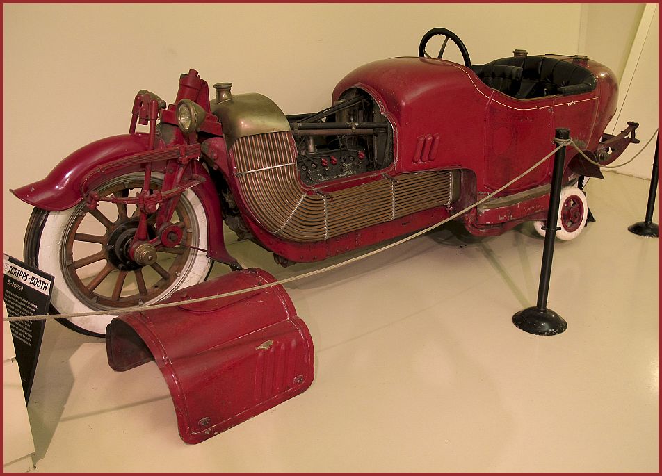
This vehicle is from a couple of decades before heat transfer engineers realized that you can make up for the much lower convective heat transfer coefficient on the air side by adding extra surface area on that side.
In this schematic the orange resistor represents the resistance (per unit length of pipe) of the copper tubes. The blue resistors represent the convective resistance (1/hA) on the outside (air side) and inside (water side) respectively. Typical values of the forced convective heat transfer coefficient from Incropera and DeWitt are: Gases: 25-250 W/m⋅K , Liquids: 100-20,000 W/m⋅K With the simple straight pipe design, the area for convection to the air on the outside is only slightly greater than the surface exposed to the liquid coolant inside the pipe. Under nearly all circumstances the much lower convection coefficient on the outside makes that resistance the “bottleneck.” Common practice now is to employ “extended surface” heat transfer, i.e., to add fins, typically made of aluminum, on the outside of the pipe.
Cross-flow Heat Exchanger Mockup

This homemade mockup shows the flow patterns in a cross-flow heat exchanger with both fluids mixed. The hot (red) fluid and cold (blue) fluids flow between alternate sheets. The dimples keep the aluminum sheets separated and promote mixing. Since there are no barriers to lateral flow for either fluid, this geometry would be considered “both fluids mixed.” Note that the surface areas exposed to each of the two fluids is the same. Thus you would use this configuration when the two fluids are similar as in an air-air heat exchanger for waste heat recovery.
Automobile heater core
In this compact automobile heater core, the liquid (engine coolant) makes two passes. In the first pass it enters the hole at the top left and flows downward through the 12 flattened tubes. When the liquid reaches the bottom plenum, it is mixed before making the second, upward pass and coming out the hole at the top right. The liquid within the core itself is “unmixed.” You can look into either hole and see that within each of the 24 flat tubes (which you are seeing in edge view in this photo), the liquid is confined to discrete channels. Similarly the air (flowing normal to this photo) is unmixed because of the cooling fins. (And note that unlike in the “honeycomb” radiator above, the surface area exposed to air is far greater than that exposed to liquid.) The coolant sees fresh air entering on both passes.
This exchanger thus corresponds to the fifth geometric configuration available with the HTT_hx program. The temperature contour plots for this geometry correspond to side views, and the two passes of the hot fluid are plotted with the first pass flipped and upstream of the second. The color plot below shows the orientation of the contour plots with respect to this exchanger.


In this partly “dissected” heater core we note plastic twisted-tape inserts being used to increase mixing of the liquid on the tube side and thus reducing that contribution to the overall thermal resistance between the liquid and air. (Photo courtesy of Bo Hosticka)
Tankless Domestic Hot Water Heat Exchanger
Here the domestic water being heated flows down and back, down and back, followed by a similar second pass. Hot combustion gases pass over the aggressively-finned outer surfaces of the pipes.
Plate Heat Exchangers
At Cornell University pumps force cold water (~ 39F = 4oC (what’s so special about this particular temperature?)) from 250’ (76m) below the surface of Cayuga Lake through seven very large counter-flow plate-and-frame heat exchangers. In these exchangers the cold lake water absorbs heat from a separate, sealed water supply that is pumped to the campus to cool buildings and equipment.
The heat exchangers used with the Lake Source Cooling Project at Cornell are gasketed plate heat exchangers. Another type of plate heat exchanger is the welded plate heat exchanger, an example of which is seen below. This type is NOT designed to be disassembled easily.

Shell-and-Tube Heat Exchangers
The Clinch River Breeder Reactor Plant was to have been built on the Clinch River some 12 miles southwest of Oak Ridge, TN. The project began in 1972 and was cancelled in 1983. Like the second U.S. nuclear submarine, the Seawolf (SSN-575), its reactor was to be cooled with liquid sodium. Before the cancellation most of the long-lead-time items, including the intermediate heat exchangers seen below, had already been fabricated. The CRBR design had three independent heat transfer loops; we show only one in the schematic.

Shell-and-Tube Intermediate Heat Exchangers (IHX) for a hypothetical LMFBR
The tubes in this single-pass, counter-flow shell-and-tube heat exchanger were over 25’ (7.5m) long. The hot sodium coming from the reactor entered the IHX at about its mid-height, traveled upward through an outer annulus and then downward through the shell and out the bottom back to the reactor core. The intermediate sodium returning from the steam generator system entered at the top, flowed downward through the center core to the bottom and back up through the 2850 tubes. Foster-Wheeler designed and fabricated the three identical IHX’s.

Shell-and-Tube Condenser
In the photo of a small shell-and-tube heat exchanger seen below, only six of the 37 tubes are in position. When the other 31 are in place, then the single-segmental baffles act as barriers, thus forcing the shell flow to take a serpentine path through the shell. In this way that fluid (in this case a condensing refrigerant) flows at nearly right angles to the tubes and the resulting turbulence increases the shell-side heat transfer coefficient.
Heat Pipe Heat Exchangers
Designers often incorporate heat pipe heat exchangers for air-to-air energy recovery systems. Three fluids participate. There are the two air streams exchanging heat. The multitude of heat pipes contain a third fluid that changes phase.

In a typical application exhaust air and fresh air are flowing in opposite directions, i.e., in a counter-flow arrangement, in adjacent ducts with the unit spanning the cross-section of both ducts. In the winter (as seen above in the schematic) heat transferred from the warm air being exhausted provides the energy to evaporate the working fluid in the sealed heat pipe. That vapor flows to the other end, where it condenses, giving up the heat to the incoming fresh air. The condensed liquid flows back to the warm end to complete the cycle.
Summer operation is reversed. The warm, but fresh, air entering the building transfers heat through the heat pipes to the cool, but stale, exhaust air leaving. To compensate for the low heat transfer coefficients typical of gases, the manufacturer fins the outside surfaces of the heat pipes aggressively.
Plate Fin Heat Exchangers
A plate-fin heat exchanger has corrugated spacers between the parting plates separating the two fluids. In the mockup of a cross-flow exchanger in this photo, offset strip fins guide the fluids in adjacent layers in perpendicular directions.

Rotary Regenerators

Fossil-fueled powerplants may use rotary regenerators to reclaim waste heat. In the very large regenerator seen in the above schematic, the hot waste stream flows downward to the left of the circumferential seal. Fresh air flows upward (countercurrent) to the right of the seal. On the exhaust side the rotating element absorbs heat in the matrix forming the rotating element. When that section of the wheel gets to the fresh air side, fresh incoming combustion air absorbs that stored heat.
“Each element weighs between 2 and 4 tons, and with the rotor and seals, it’s a 200 ton, 20 ft diameter rotating assembly turning at about 1.5 rpm. The regenerator heats incoming air from 100 degrees F to 500 degrees F. The exiting flue gas drops from 600 degrees F to about 250 degrees F. We do periodic inspections on the elements to ensure that the corrugated steel heat transfer surface is in good shape…” (Dan Moses, Potomac Electric Power Company).

Chrysler Turbo Car
The experimental Chrysler turbo car of the 1960’s and 70’s incorporated the Brayton cycle with regeneration:
Gases leaving the power turbine (which rotated at speeds as high as 70,000 RPM) passed through either of the two slowing rotating regenerators (which rotated at much more leisurely speeds up to a maximum of 31 RPM). One-hundred eighty degrees away, the ceramic material making up the rotor gives up the heat just stored to the relatively cool air coming from the compressor.
This setup saves the heat needed to raise the charge temperature from 430F to 1200F (see schematic above). The exploded view below shows the hardware including the regenerators. (Photos courtesy of T.C. Scott.)

Software for analysis and design of Heat Exchangers:
- HTT_HX.exe Visual Studio executable for the design and analysis of multiple heat exchanger geometries.
- Effectiveness-NTU Relations Excel workbook covering one of the two conventional (pre-computer) methods for heat exchanger design and analysis
References:
Incropera, F.P., and DeWitt, D.P., Fundamentals of Heat and Mass Transfer, 5th Ed., Wiley, New York (2002)
Shah, R.K. and Sekulic, D.P., Fundamentals of Heat Exchanger Design, Wiley, New York (2003)
Des Champs Laboratories Incorporated, Heat Pipe Heat Exchanger, Bulletin HPHX1193/1.0, 1993.
Valeo, Il “Radiatore” Nel Tempo, 2nd Edition, 1984.